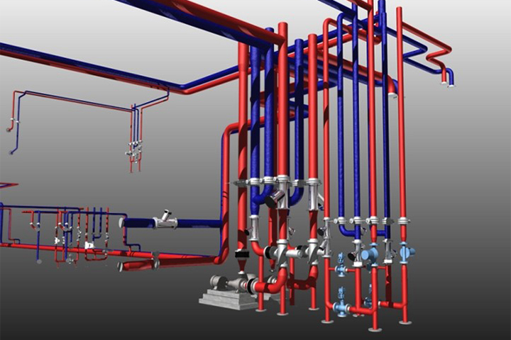
circuit setter piping diagram
MechEngNCPE Mechanical 15 Feb 11 1250. Piping and Instrumentation Diagrams are graphical representations of a process system.
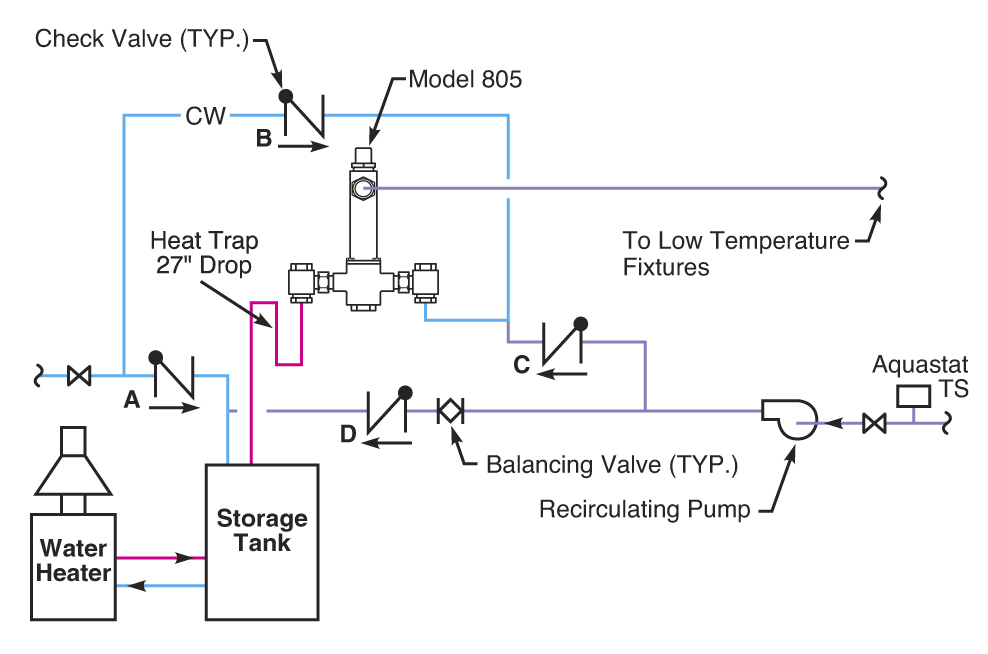
Plumbing Topic Domestic Water Recirculation Systems Part 7
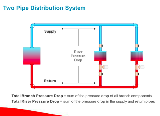
Adjust pump flow so that circuits are receiving their.

. Using Side 1 of the V91483 Circuit Setter Balance Valve Calculator set the degree of. This Circuit Setter is left in the full open position. Products range from Balancing Control Valves AirDirt Separators Air Vents and Expansion Tanks.
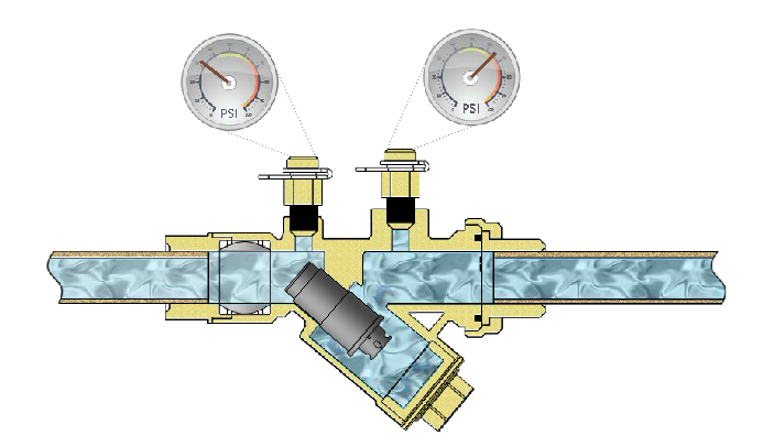
In this Service Tip of the Month video we discuss and demonstrate the operation of reading adjusting and setting a Bell Gossett Balance Valve. This plumbing valve is used to regulate the flow of water. The circuit setter was developed by Bell Gossett so as to.
Circuit setter valves plus balance calibrated valve flow balancing water hydronic bell gossett manual hvac system curves. This Circuit Setter is left in the full open position. Nexus offers solutions in hydronic heating and chilled water cooling systems.
D pipe diameter. PID is an abbreviation meaning Piping and Instrumentation Diagram. Circuit setter piping diagram.
Every other Circuit Setter in the branch is then reset to the same proportional flow rate. DP Control With Variable. This Circuit Setter is left fully open and the other riser Circuit Setters are adjusted to this same ratio as descr ibed in Step 5 above.
Commercial Electric Heat Pump. Select the appropriate size Circuit Setter Balance Valve normally line size for the required GPM. The minimum pipe size for connecting a Super Stor water heater is 1.
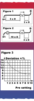
A minimum of 6 pipe diameters of straight pipe shall be installed upstream and downstream of all closely spaced tees. If there are additional branches repeat the. Circuit setter piping diagram.
Commercial Tank Type Gas. Commercial Tank Type Electric. Bell Gossett Circuit Setter Plus has revolutionized the plumbing system.
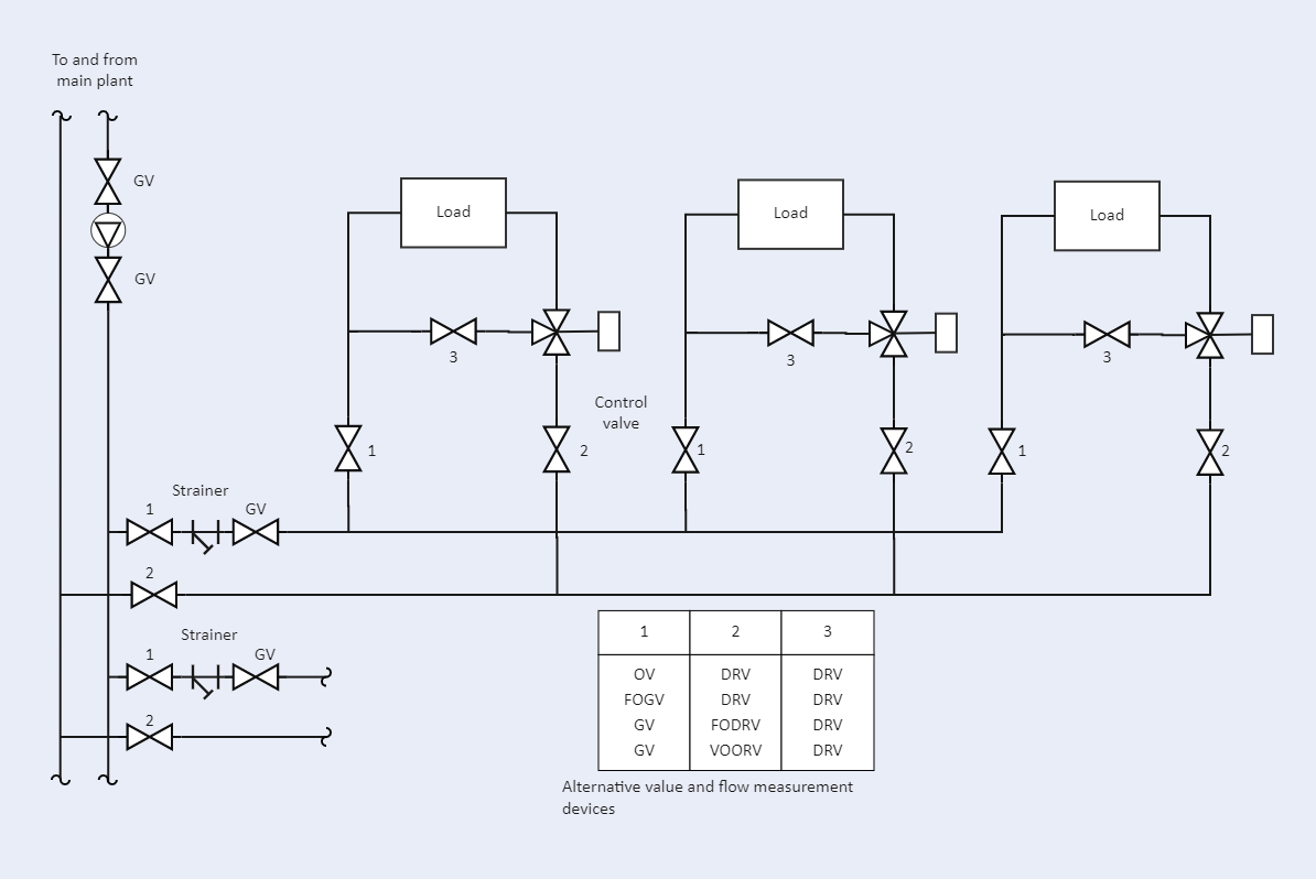
BG 117113 - CB 5 Flanged Cast Iron Circuit Setter Balancing. Install the valve in the correct flow. PIPING Piping Symbol Legend circulator w isolation flanges gate valve globe valve ball valve swing-check valve flow-check valve spring-loaded check valve hose bib boiler drain.
Size header piping so flow velocity does not exceed 4 ftsecond under design load flow conditions 11. 11 circuit setter piping diagram. A minimum of 6 pipe diameters of straight pipe shall be installed upstream and downstream of all closely.
Circuit setter piping diagram. Grommet labs Piping typical field wiring Modeling a circuit setter balancing valve Bg 117105 Bg 1-14 circuit setter Circuit setter balancing flanged bell. Circuit setter bell gossett balancing valves cb flanged grooved diagram valve.
Domestic Circulating Water Heaters. 12 Images about Circuit Domain Projects. Install the valve in the correct flow direction according to the arrow on the valve body and the distance parameters detailed in Figure 1 Note.
PIDS are foundational to the maintenance and modification of the process that it graphically represents. At the design stage the diagram also provides the basis for the development of. Circuit setters generally are installed at the end of a heating hot water loop to allow there to be continuous flow through the.
Circuit Setter Piping Diagram Edrawmax Template

Types Of Balancing Devices For Systems With Variable Speed Pump Control

A New Approach To Variable Flow Hydronic Systems Pm Engineer

Parallel Pumping In Condenser Applications Part 2 Of 5
Balancing Hvac Hydronic Systems Part 4 Automatic Flow Limiting

Flow Balance Valve Location Supply Or Return Side Of The Coil

Thinksystem Heavy Duty Rack Cabinets Water Specifications For The Secondary Cooling Loop
Circuit Diagram Collection Templates Edrawmax Free Editable

Balancing Valve An Overview Sciencedirect Topics

Zone Balancing Boiler Protection Buffer Piping Control Heating Help The Wall

Zone Balancing Boiler Protection Buffer Piping Control Page 2 Heating Help The Wall
Manual Balancing Valves For Hydronic Balancing Danfoss
Balancing Hvac Hydronic Systems Part 3 Flow Measurement Valves

B G 117105 Cb 2 Npt Brz Circuit Setter Balancing Valve
Installation Flow Tunstall

Bell Gossett Circuit Setter Plus Calibrated Balance Valves Xylem Us
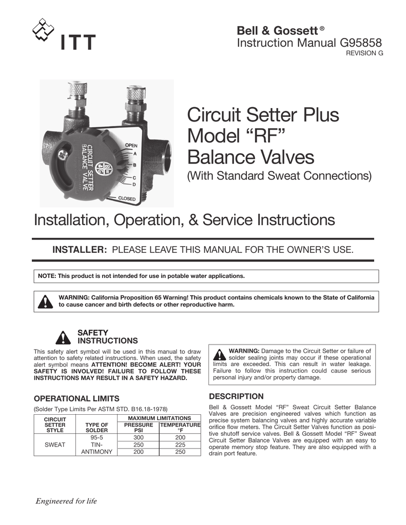
Circuit Setter Plus Model Rf Balance Valves Installation Operation Service Instructions Manualzz